
Ask two labs what pressure they press their sulfide pellets at, and you will often get two different answers — and a third lab may report neither. Pressure is the most under-reported variable in solid-state cell testing, yet it sits behind the two most common failures: pellets that crack during assembly, and cells whose impedance drifts for the first fifty cycles.
Part of the confusion is that "pressure" names two different numbers, applied by two different pieces of hardware, at two different moments of the experiment. This article separates them, gives typical values for the common electrolyte systems, and lists the minimum fields to write down so the numbers stay comparable with the literature.
Why Solid-State Cells Need Pressure at All
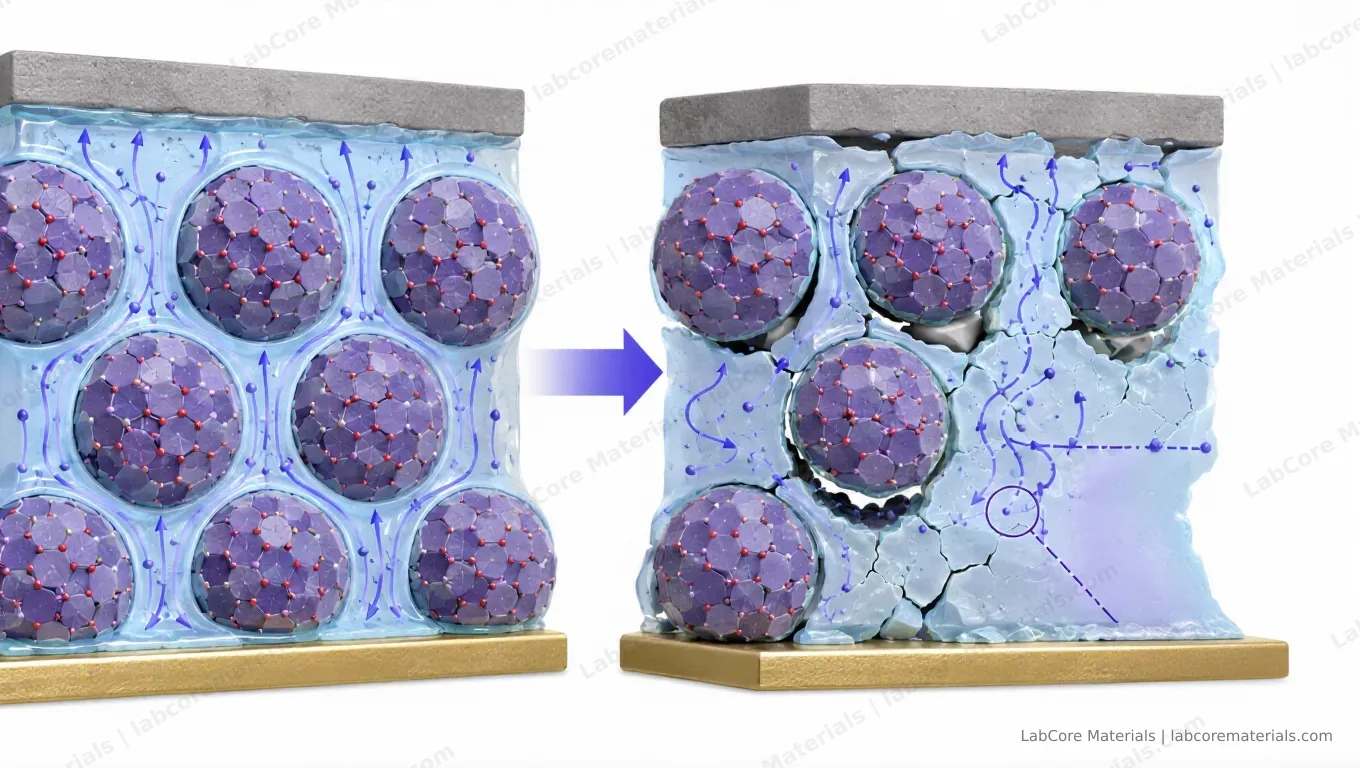
In a liquid-electrolyte cell, the liquid wets every surface and fills every gap. A solid electrolyte does neither. After cold pressing, solid-solid interfaces are never perfectly flat: microscopic voids remain between the electrolyte and the electrode particles, and those voids concentrate current into a few contact spots. The spots carry disproportionate current, lithium deposits preferentially there, and the contact area shrinks further — the feedback loop that ends in a short circuit.
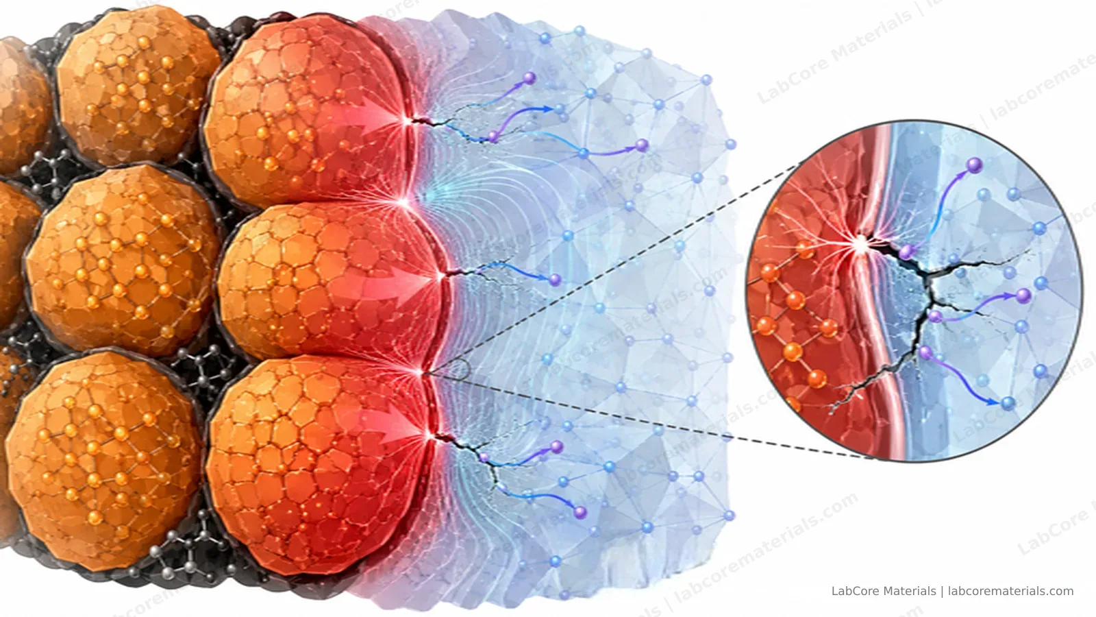
Pressure addresses this mechanically. Holding the stack under compression keeps particle contacts closed, slows void growth during cycling, and maintains the ion pathways. Every high-performing sulfide lab result you read was measured under a defined, held pressure. If your cell has none, you are not running the same experiment.
Contact quality also degrades over cycling even when the initial press was good: particles deform, the cathode composite breathes as lithium enters and leaves, and any gap that opens concentrates current at its edges.
Two Pieces of Hardware, Two Pressures
The terminology sorts itself out once each pressure is mapped to the hardware that applies it. Most labs already own both pieces; what is usually missing is the discipline to name them separately.
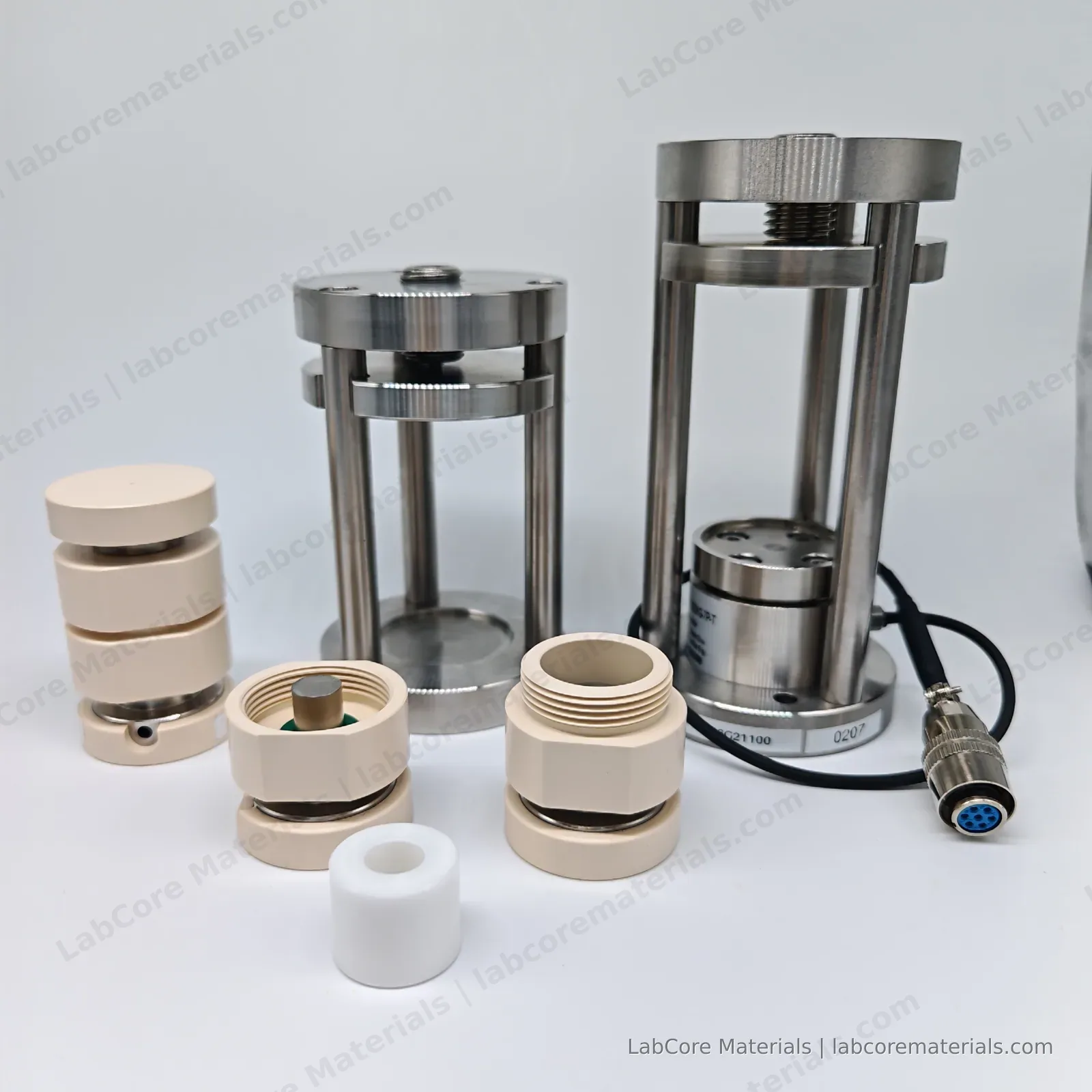
The solid-state battery mold does two jobs in one body. It is a sealed chamber first: split-cell construction with O-ring seals isolates the powder — or the assembled cell — from ambient air and moisture, which is why solid-state assembly happens inside a glovebox and the mold travels in and out through the transfer chamber. It is also a pressing device: placed under a press, its plungers compact the powder, the electrolyte layer, or the whole stack. The pressure applied at this moment is the forming pressure — a one-time compaction step whose target is density.
The external pressing fixture takes over once the cell is assembled. A cell under test needs mechanical load that is applied and held: rigid plates with locking screws, or spring-loaded plungers, keep the stack compressed while the electrode layers breathe over hundreds of cycles. The load the fixture maintains during operation is the test pressure — written as "operating stack pressure" in much of the literature — and its target is contact.
Two consequences follow directly:
- Forming pressure exists only at the moment of compaction. The plunger releases, and it is gone. A pellet pressed at 300 MPa is not "a cell operating at 300 MPa"; after assembly the stack may be held at 10 MPa or less.
- Test pressure drifts unless the fixture compensates. A rigidly locked fixture loses force as the stack relaxes and as layers expand and contract with temperature and state of charge; a spring-loaded one holds the force roughly constant over its travel. Which scheme was used changes how the reported number should be read.
Reports quoting a single pressure number should always be read with that question in mind: which one is it?
Typical Values: Powder, Film, and Cell
Forming and test pressures span different ranges for each electrolyte class. For sulfides the two sit roughly an order of magnitude apart:
| System | Powder forming | Film / composite layer | Test pressure (cycling) |
|---|---|---|---|
| Sulfide (Li6PS5Cl, Li10GeP2S12) | Cold press 100–500 MPa; 300–400 MPa common | Tape-cast or slurry film laminated by warm pressing, tens of MPa | 5–50 MPa in lab cells; below ~10 MPa for production targets |
| Oxide (LLZO, LATP) | Cold press 200–500 MPa to a green body, then sinter — pressure alone does not densify it | Sintered ceramic sheet; lamination is replaced by surface finishing | Single-digit MPa; surface preparation matters more than load |
| Polymer / composite | Hot press or tape casting at elevated temperature | Calendered membrane | Single-digit MPa; constant-force fixturing preferred — the load relaxes |
Halide electrolytes can also be cold-pressed into pellets and are often paired with Li–In anodes, cycled at single-digit MPa or lower.
Three readings of the table worth spelling out:
- Sulfides owe their processability to pressure. Soft sulfide particles deform plastically under the press, which is why cold pressing alone reaches above 90% relative density — and why the forming pressure (hundreds of MPa) sits an order of magnitude above the test pressure (a few to tens of MPa). Both numbers matter, and they are not interchangeable.
- For oxides, the press only makes a green body. Densification happens in the sintering furnace. By the time the cell is tested, the sintered ceramic is already dense, so the fixture's job is keeping contact, not adding density — and excessive load on a brittle garnet does more harm than good.
- For polymers, track the force instead of assuming it. Viscoelastic layers creep under sustained load, so a fixed-gap fixture silently loses pressure. Constant-force fixturing with the force logged alongside the electrochemistry is the cleaner experiment.
From Tonnage to MPa: The Conversion
Presses are labeled in tons of force; the literature reports pressure in MPa. The conversion runs through the punch area:
where F is the applied force and d is the die bore diameter. One metric ton of force is 9,806.65 N, so the pressure per ton depends entirely on the diameter:
| Die bore | per 1 t | 2 t | 3 t | 4 t | 5 t |
|---|---|---|---|---|---|
| φ10 mm | 125 MPa | 250 MPa | 374 MPa | 499 MPa | 624 MPa |
| φ12 mm | 87 MPa | 173 MPa | 260 MPa | 347 MPa | 434 MPa |
| φ16 mm | 49 MPa | 98 MPa | 146 MPa | 195 MPa | 244 MPa |
Read the table from the direction of the target pressure. To compact a sulfide pellet at 300–400 MPa in a φ10 mm die, you need roughly 2.5–3 t; the same 3 t on a φ16 mm die delivers only 146 MPa — under-pressed, likely porous. A φ10 mm bore under a 5 t press tops out at 624 MPa, enough to cover the entire sulfide forming range above. A 5-ton press means nothing without the die diameter next to it.
How to Apply Each Pressure
Forming pressure goes in through the mold. Practical points that matter as much as the number:
- Approach the target load slowly — over tens of seconds, not seconds — and hold a defined dwell, typically one to several minutes, so the powder densifies rather than springs back.
- Release slowly too. Abrupt unloading is a common cause of end-cap delamination and hairline cracks that only show up as impedance scatter days later.
- Ejection friction depends on the die wall. A ceramic-lined bore (zirconia is the standard choice for sulfide work: chemically inert toward the powder and trace H2S, and it introduces no metallic contamination) ejects cleaner than uncoated tool steel.
This is the workflow the single-point pressing solid-state battery mold (MOL5B100A) was designed around: a φ10 mm PEEK-ceramic cavity suited to glovebox operation, 5 t stack force covering the sulfide forming range, and an optional integrated load sensor (500–5000 kg ranges) that replaces "the gauge said" with a measured force. For frequent sample changes, the locking-ring compact mold (DLK-MOL1B100A) adds a fast, even pressure release — the pellet is not shocked at unload, which is exactly when most hidden cracks are born.
Test pressure is a fixturing decision. The two common families:
- Rigid clamping — the assembly is locked to a fixed height, the stack gap is constant, and the force drifts as the stack relaxes. Simplest to build, easiest to underestimate.
- Spring-loaded — a spring stack holds a roughly constant force over a defined travel range and absorbs the breathing of the cell; the spring itself relaxes over time and its calibration is rarely re-checked.
Neither is universally better; what matters is stating which one was used, because a rigid fixture and a spring fixture produce different effective pressure histories even from identical starting values. The three-point pressing solid-state battery test mold (MOL5A100A) pairs a dual-seal split-cell mold with an external fixture whose three-point geometry distributes the stack force more evenly across the electrode/electrolyte interface — a practical advantage with brittle oxide pellets, thin lithium-metal foils, or pressure-sensitive sulfide layers. The sensor-equipped variant reports the actual force on the stack, not the torque applied last week.
The Common Errors
- Quoting tonnage without diameter. "Pressed at 5 t" is 624 MPa in a φ10 mm die and 244 MPa in a φ16 mm die — a factor of 2.6 between two sentences that sound identical.
- Quoting the wrong pressure. Reporting the forming pressure as the test pressure, or the reverse, makes the number irreproducible even if both are individually sensible.
- Ignoring relaxation. Polymer gaskets, PEEK insulators and spring stacks all creep. A stack set to 10 MPa at assembly may sit measurably lower after a week at 60 °C. For long experiments, re-check the load or acknowledge the drift explicitly.
- Skipping dwell time. Two pellets pressed at the same peak pressure with different dwell times come out with different densities. Dwell belongs next to the pressure in the report.
- Cracking on release. Pellets that survive pressing but crack during punch release are common when unloading is abrupt. The cracks often do not reach the surface, so the pellet looks intact — until the impedance data says otherwise.
What to Report: The Minimum Fields
A pressure figure is only reproducible alongside its context. The minimum set:
- Die bore diameter, and whether the bore is bare steel or ceramic-lined
- Forming pressure in MPa (not tons), with dwell time, and release speed if it was unusual
- Test pressure during cycling, and the fixturing scheme (rigid or spring-loaded)
- Temperature during pressing and during cycling
- Pellet dimensions after pressing — thickness and diameter, because they change
Five fields, one line in an experimental section. The payoff is comparability: a conductivity measured at 300 MPa forming pressure in a φ10 mm ceramic-lined die, cycled at 10 MPa under a spring-loaded fixture, can be compared with the literature; the same number measured at "5 tons" cannot. Janek and Zeier list pressure management among the practical challenges that decide whether lab results survive scale-up (Janek & Zeier, Nat. Energy, 2023, 8: 230–240), and direct stack-pressure dependence of lithium stripping/plating in sulfide cells confirms the effect is not subtle (Asakura et al., ACS Appl. Mater. Interfaces, 2023, 15: 31403–31408).
What the Data Are For
Once the pressure context is pinned down, the numbers start working for you instead of against you:
- Troubleshooting. Impedance that grows over the first cycles points to contact loss — a test pressure problem — before it points to a chemistry problem. Checking the fixture is cheaper than replacing the electrolyte.
- Reproducing an experiment. A literature protocol is only reproducible when the pressure fields come with it. With them, "300 MPa forming, φ10 mm, 2 min dwell, 10 MPa test pressure, spring-loaded" is a recipe; without them, it is a rumor.
- Choosing tooling. Knowing the target pressure and the die diameter tells you the tonnage class you actually need — and, if you work with sulfides, the moment to insist on a ceramic-lined bore.
The pressure you apply is part of the experiment definition, not an implementation detail. Write it down as such — both of them — and your data stay comparable across cells, across months, and across labs.
Further Reading
- Kato et al., Nat. Energy, 2016, 1: 16030 — high-power sulfide cells; the conductivity benchmark that made sulfides the leading electrolyte class.
- Schnell et al., J. Power Sources, 2018, 382: 160–175 — scale-up pathways, where pressure handling becomes a production parameter.
- Janek & Zeier, Nat. Energy, 2023, 8: 230–240 — the field's challenges review, with interface and pressure management among the decisive items.
- Asakura et al., ACS Appl. Mater. Interfaces, 2023, 15: 31403–31408 — direct stack-pressure dependence of Li stripping/plating performance in sulfide cells.