
In all-solid-state battery experiments, most failed runs and rework originate not in the electrochemistry but in sample handling: an electrolyte pellet that survives pressing cracks during disassembly, plungers seize after high-temperature cycling, and a stack pressure that was never recorded later becomes the variable invoked to explain batch-to-batch scatter.
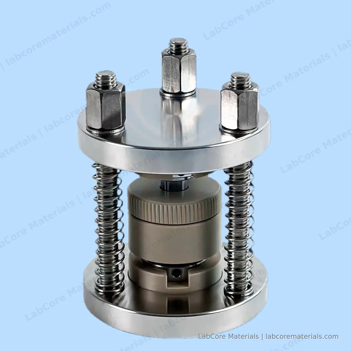
Liquid cells tolerate rough handling; solid-state cells do not. This article walks through the complete cycle of a solid-state experiment on the locking-ring test mold — pellet pressing, assembly, testing and controlled release — and states the experimental conditions each step must hold.
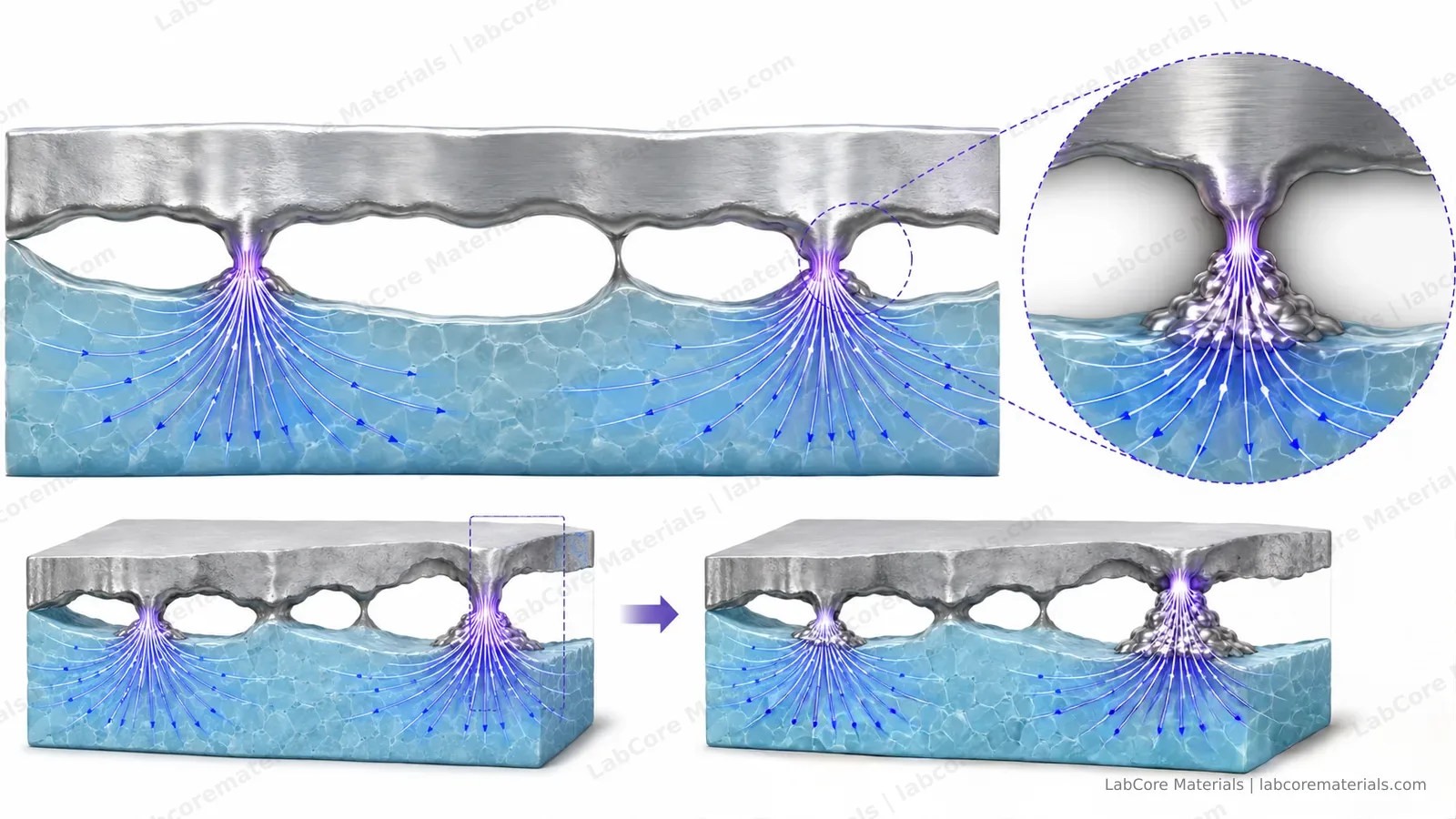
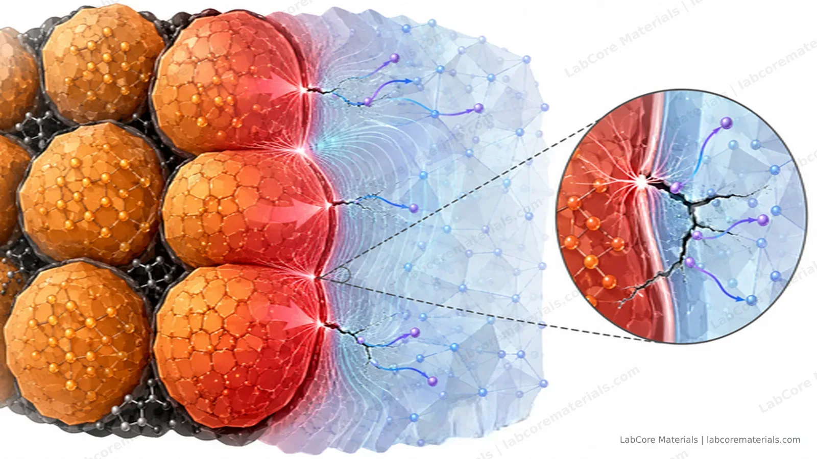
Why solid-state clamping differs from liquid-cell practice. In a liquid cell, the electrolyte wets the electrode surface and interfacial contact is maintained by the liquid phase. In an all-solid-state cell the contact is solid–solid: ionic conduction across the electrode/electrolyte interface occurs only where the two surfaces are actually pressed together. Interfacial voids do not merely add contact resistance; they redistribute the current into the remaining contact area, raising the local current density — a primary trigger for dendrite nucleation and localized heating. As cycling proceeds, volume changes of the electrode materials accumulate mechanical stress at the boundary, and the contact state evolves continuously.
Stack pressure in a solid-state experiment should therefore be managed as an experimental parameter, on the same level as temperature and voltage window. It affects the conductivity values obtained by EIS (treated in detail in our impedance interpretation guide) and it determines the interfacial contact state. Once a pressure value goes unrecorded, no post-hoc analysis can recover it as a controlled variable. The baseline requirements for a solid-state fixture are consequently twofold: hold the stack pressure stable throughout cycling, and make the actual pressure value known.
Where conventional disassembly fails. A pressed sulfide or oxide electrolyte pellet is a brittle ceramic disc held between two steel plungers under several hundred megapascals. Releasing the load by unscrewing the lead screw does not lower the stack pressure uniformly: the elastic energy stored in the plungers discharges along the least rigid path, which is generally the pellet itself, producing cracks or adhesion between the disc and the plunger face. Inside a glovebox, where transfers are constrained and a broken pellet means a full re-pressing cycle, the rework cost is multiplied.
The locking ring addresses this failure mode structurally. Release is divided into two stages: after testing, the upper locking ring first carries the clamping load and relaxes it gradually and evenly; only when the stack pressure has fallen to near zero do the plungers separate. The release rate remains under the operator's control. For laboratories cycling large sample volumes, this translates into fewer fractured pellets, reduced wear on the PEEK core and plunger surfaces, and shorter glovebox time per sample change.
Materials and ratings. The mold core is PEEK: electrically insulating, chemically inert toward sulfides, and mechanically adequate at operating temperatures up to 200 °C. The plungers are die steel. The assembly is rated to 4 t of stack force, corresponding to 500 MPa on the standard 10 mm cavity; a 1000 MPa custom version is available for densification studies requiring higher pressures. The cavity diameter is 10 mm as standard, customizable from 5 to 20 mm, so that electrode area can follow the experimental design. External dimensions are φ70 × 93 mm, allowing pressing through release to be carried out entirely inside a glovebox.
A representative working day. The workflow below uses the locking-ring mold as the anchor; the other two solid-state molds appear where their features apply:
- Pellet pressing. Electrolyte powder is pressed into a disc. For process-control work, the three-point pressing mold with the integrated pressure sensor records the compaction pressure.
- Assembly in the glovebox. The electrolyte disc is stacked with the electrodes and loaded into the mold; the stack is brought to the target pressure. The working/counter two-electrode configuration covers cycling and symmetric-cell impedance measurements.
- Testing. Cycling, or EIS for conductivity and interface diagnostics. Spectra are read with the bulk / grain-boundary / interface framework from the impedance interpretation guide. Where impedance must be attributed to a single interface, the solid-state three-electrode mold with its built-in reference electrode provides the answer directly.
- Release and disassembly. The locking ring relaxes the stack in stages; the mold is opened and the pellet removed intact; the fixture proceeds to the next sample.
None of these steps is remarkable in itself. Their value lies in that the experimental conditions at the fixture — pressure, contact state, release path — are explicit and controlled, which is what makes solid-state data comparable between samples and between campaigns.
Which mold for which task.
| Task | Fixture | Rationale |
|---|---|---|
| Frequent sample changes, cycling | Locking-ring mold | Staged, even release protects pellets and the PEEK core |
| Pressing with recorded pressure | Three-point pressing mold | Integrated pressure-sensor option |
| Impedance attribution to a single interface | Solid-state three-electrode mold | Built-in reference electrode |
Application cases
| Source | Setup | Observation |
|---|---|---|
| Bruce P G. Solid State Ionics, 1987, 25: 255–262. DOI: 10.1016/0167-2738(87)90189-5 | DC technique for measuring solid-electrolyte conductivity | DC polarization under ion-blocking conditions — the standard route to electronic conductivity, and the origin of the pressure and contact discipline in conductivity measurements |
| Wang J, Bates J B. Solid State Ionics, 1986, 18–19: 224–228. DOI: 10.1016/0167-2738(86)90116-5 | Interfacial impedance model for a solid electrolyte against a blocking metal electrode | Analytical model of solid–solid interface impedance — the theoretical reference for reading the interface arc in solid-state spectra |
Conclusion
Maintaining stack pressure and interfacial contact under explicit control across the full cycle from pellet pressing through cycling to staged release establishes reproducible conditions for all-solid-state battery measurements. Conductivity values, impedance spectra and cycling data acquired under these conditions are comparable across samples and measurement campaigns, and provide an experimental basis for studying interfacial evolution, conduction decay and mechanical degradation in solid-state systems.