
Why there is no single answer
Nobody agrees on electrolyte volume for a CR2032, and the disagreement is not really about the cell — it is about the experiment. The volume that maximizes cycle life is the wrong volume for a rate test. The volume that is appropriate for carbonates is not valid for sulfides. So instead of one number, this guide gives a decision table, a way to calculate your own, and the symptoms that tell you the volume was wrong before you lose three weeks of cycling.
One principle first: within a comparison series, the exact volume matters far less than keeping it identical. A series where every cell got exactly 80 µL is interpretable. A series where volumes wandered between 60 and 100 µL is not, no matter what the absolute value was.
The baseline
For a standard CR2032 half cell with 15.6 mm electrodes:
| Parameter | Value |
|---|---|
| Electrode area | ≈ 1.9 cm² |
| Typical areal loading | 2–4 mAh/cm² |
| Cell capacity | ≈ 4–8 mAh |
| Baseline dosing | 60–120 µL |
| Resulting E/C ratio | 15–30 µL/mAh |
That 60–120 µL window covers most carbonate-based screening work. Where you sit inside it depends on the test — see the table below. For context, commercial cells run 1–3 µL/mAh, so a research coin cell is always testing your material in a generous electrolyte environment (see why that changes your numbers).
Dosing by experiment type
| Test type | Dosing | E/C target | Reasoning |
|---|---|---|---|
| First-cycle CE / capacity screening | 60–80 µL | 15–20 µL/mAh | Standard conditions; enough reserve for wetting variability between cells |
| Long cycling (> 500 cycles) | 80–120 µL | 20–30 µL/mAh | Electrolyte is a consumable; extra volume offsets decomposition over months |
| Rate tests (2C–10C) | 40–60 µL | 8–15 µL/mAh | Less flooding sharpens ionic-path differences; but pipetting tolerance gets critical |
| Gassing-prone systems (Si, high-voltage) | 50–80 µL | 12–20 µL/mAh | Excess electrolyte increases the decomposition reservoir; moderate fill keeps gas readable |
| Sulfide / ionic-liquid electrolytes | 10–30 µL | 3–8 µL/mAh | Material is expensive and viscous; wetting kinetics, not volume, is the constraint |
Two notes on the extremes:
- Do not chase the commercial 1–3 µL/mAh in a coin cell. Below roughly 5 µL/mAh, wetting becomes irreproducible and cell-to-cell scatter increases sharply. If lean electrolyte is the research question, move to a single-layer pouch cell where fill ratio is actually controllable.
- Rate tests punish sloppy pipetting. At 40 µL, a ±10 µL error is a 25% difference in E/C. Use a calibrated positive-displacement pipette, not a variable "air cushion" one — organic electrolytes wet the standard tip poorly, and the error is systematic.
Calculating your own number
Worked example: NMC532 at 3 mAh/cm² on 15.6 mm electrodes.
- Area: π × (0.78 cm)² ≈ 1.91 cm²
- Cell capacity: 3 × 1.91 ≈ 5.7 mAh
- Target E/C = 20 µL/mAh (screening)
- V = 20 × 5.7 ≈ 115 µL
Same cell at a lean 8 µL/mAh (rate arm): ≈ 45 µL. Same calculation, two very different pipette settings — which is exactly why the raw "µL" number means nothing without the E/C context.
Under-dosing: symptoms that appear before the data fails
Under-dosing shows clear early warning signs, usually within the first five cycles:
- OCV drifts downward after assembly instead of stabilizing — the separator is not fully wetted.
- 1 kHz impedance starts high and keeps climbing through the first cycles as wetting proceeds unevenly.
- Capacity fluctuates cycle to cycle (not fades — fluctuates), because parts of the electrode participate intermittently.
- First-cycle CE drops 1–3 points below what the system normally delivers.
- On teardown: a visible dry ring at the electrode edge, or the separator peels back dry.
If you see two or more of these together, the series is already compromised — stop and re-dose rather than cycling to 500 and wondering.
Over-dosing: subtle, but not harmless
Over-dosing rarely ruins the electrical data, which is exactly why it often goes unnoticed:
- Electrolyte weeps from the crimp rim during or right after sealing. Wipe it, and you have also wiped salt residue off the case — now the cell looks fine and the gasket area is contaminated.
- The crimping die gets coated over a series of cells; the residue transfers to the next batch.
- The outer case surface corrodes in storage, especially with halogenated salts.
- In the worst case, excess liquid wicks into the gasket interface and creates a soft short that comes and goes — the most troublesome failure mode in coin cell work.
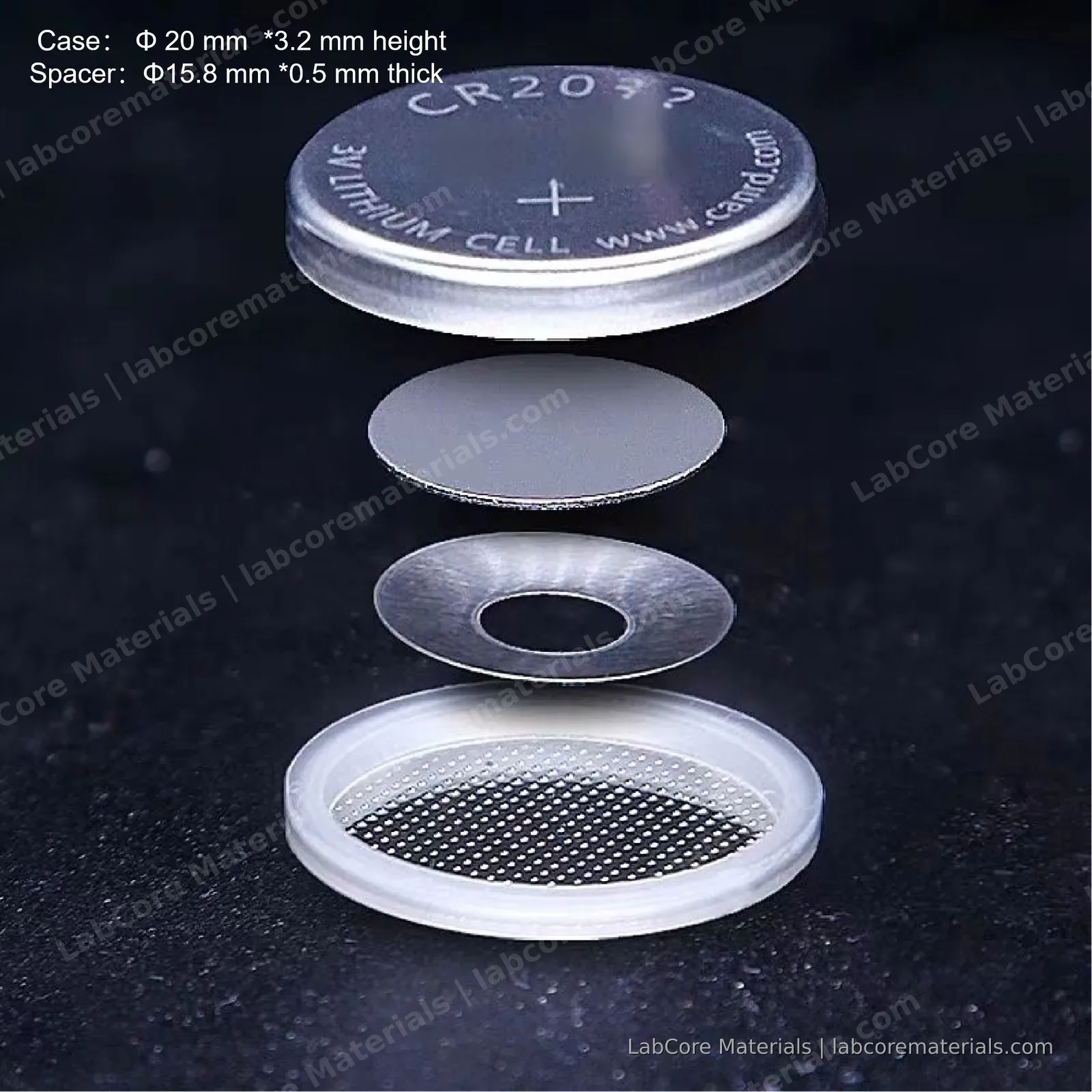
The practical ceiling for a CR2032 with a standard 0.5–1.0 mm spacer stack is around 120 µL; beyond that you are filling the gasket groove, not the cell.
The procedure that keeps it honest
- One pipette, one setting, one series. Set the volume once; do not adjust between cells.
- Dose onto the separator center, not the case wall — liquid on the wall finds the gasket first.
- Rest 2–4 hours before crimping so wetting proceeds in the assembled stack, then crimp.
- Log the volume, salt, and lot for every batch. Reviewers ask; so do collaborators six months later.
- Assemble n ≥ 3 per condition. The scatter between identically dosed cells is your real error bar, and it is usually bigger than people assume.
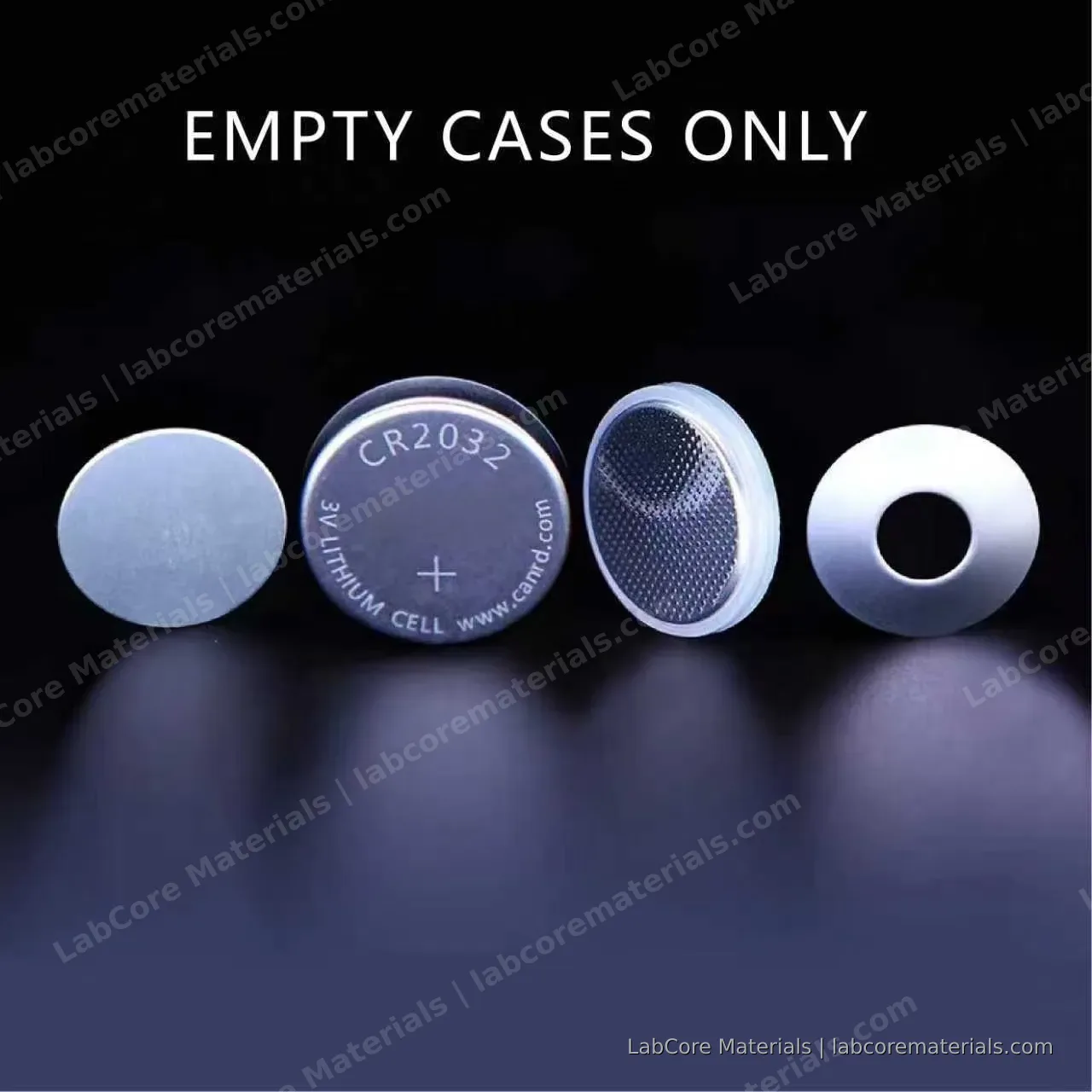
For the full assembly sequence — stack order, crimping force, common failure modes — see the CR2032 assembly guide. The CR2032 kit ships with matched cases, spacers and springs so the mechanical side of the volume calculation stays fixed.
Questions about dosing protocols or electrolyte handling? Contact the team.