
Advantages and Bottlenecks of Sulfide Electrolytes
Sulfide solid electrolytes are attractive for two practical reasons. First, their room-temperature conductivity is the highest among the main electrolyte classes: Li10GeP2S12-type conductors reach the 10 mS/cm range at 25 °C (Kato et al., Nat. Energy, 2016, 1: 16030). Second, argyrodite-type Li6PS5X powders densify by cold pressing at laboratory pressures, so a working pellet needs no high-temperature sintering step. Both properties explain why sulfides dominate the all-solid-state cell literature.
The same properties, however, do not carry the cell through cycling. In published cell data, the resistance that grows with storage, with cycling, or with a badly pressed pellet almost always traces back to an interface — cathode/electrolyte, lithium/electrolyte, grain boundaries inside the pellet, or the electrolyte's reaction with air and moisture. This article separates these four locations, describes the mechanism at each, and lists what a laboratory can actually control.
The Cathode Side
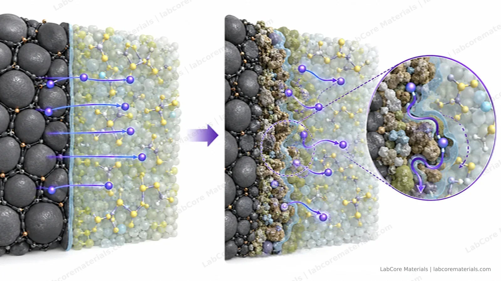
When a bare oxide cathode particle touches a sulfide electrolyte, two processes start at the contact.
The first is an electrostatic one. The chemical potential of lithium differs between the oxide and the sulfide, so Li+ redistributes across the boundary until the electrochemical potentials line up. The result is a lithium-depleted layer on the electrolyte side — the space-charge layer — which contributes impedance well before any chemical reaction occurs. First-principles calculations for the LiCoO2/Li6PS5Cl contact quantify this depletion and its contribution to interfacial resistance (Haruyama et al., Chem. Mater., 2014, 26: 4248–4255).
The second is a chemical one. Sulfide electrolytes are thermodynamically unstable against high-voltage oxide cathodes: the sulfide oxidizes at the contact, the reaction products are poorly conducting, and the interfacial resistance climbs with time and voltage.
Both problems respond to the same countermeasure: an interposed coating on the cathode particle. A thin LiNbO3 layer on LiCoO2 suppresses the interfacial reaction and markedly lowers the interfacial resistance of cold-pressed all-solid-state cells (Ohta et al., Electrochem. Commun., 2007, 9: 1486–1490). Building on that approach, LiNbO3-coated LiCoO2 paired with an LGPS-type electrolyte delivered room-temperature all-solid-state cells with power characteristics approaching liquid-electrolyte systems (Kato et al., Nat. Energy, 2016, 1: 16030). Our earlier article on coating thickness thresholds covers this strategy in detail.
The Anode Side
Against metallic lithium the problem reverses. Sulfide electrolytes are reduced rather than oxidized at the contact, and the reduction products form a layer whose quality decides whether lithium deposits uniformly. When the solid-solid contact is incomplete — as it always is to some degree after cold pressing — voids concentrate the current into a few contact points, and those points are where lithium deposits first.
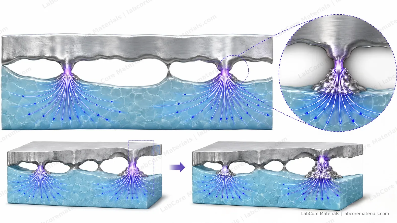
The deposits grow into the voids, the effective contact area shrinks, and the local current density rises further — a feedback loop that ends in dendrite penetration or an internal short. Practical cell data reviewed in the literature treat interfacial instability and dendrite growth as the central obstacles to practical sulfide cells, alongside processing and manufacturing constraints (Kerman et al., J. Electrochem. Soc., 2017, 164: A1731–A1744).
Laboratory cells usually soften this problem with alloy anodes. An Li–In or Li–Al electrode replaces bare lithium metal: the alloy deforms under stack pressure, conforms to the electrolyte surface, and deposits lithium at lower polarization. The trade-off is a lower cell voltage, so a comparison made with an alloy anode does not transfer directly to a lithium-metal cell.
Air and Moisture
Sulfide electrolytes react with water vapor and release H2S, a toxic gas, and the hydrolysis also degrades the electrolyte itself. This is the strictest operational boundary between sulfide work and liquid-electrolyte work: weighing, transfer, pressing and cell assembly all happen inside an inert glovebox, and exposed handling time is kept short even there.
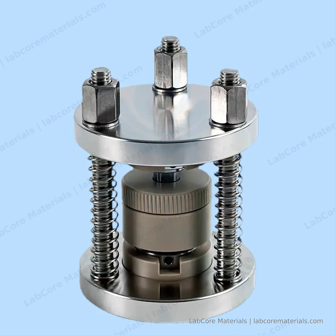
The consequence for equipment is direct. Anything that touches the powder — dies, plungers, spatulas, Pellet press platens — must survive glovebox service without outgassing or corrosion, which is why PEEK- and ceramic-bodied dies are preferred for sulfide pressing. Steel components are acceptable but should be cleaned and dried before every glovebox entry, because surface moisture rides in with the tooling. The LabCore solid-state battery test molds are built around this requirement: the zirconia ceramic liner is chemically inert toward sulfides and trace H2S and introduces no metallic contamination into the sample, while the 440C stainless steel plunger balances strength with corrosion resistance and holds up in long-term glovebox service.
Solid-Solid Contact and Stack Pressure
Without a liquid to wet the particles, ionic transport across a cold-pressed pellet depends entirely on how well the powder densified. Composition sets the ceiling: the Ge-substituted argyrodites Li6+xP1−xGexS5Cl raise room-temperature conductivity above 10 mS/cm by tuning lattice polarizability (Kraft et al., J. Am. Chem. Soc., 2018, 140: 16330–16339). The pressing step decides how much of that ceiling a real pellet keeps.
Three pressure-related effects show up repeatedly:
| Condition | What it does to the cell | Practical sign |
|---|---|---|
| Pressing pressure too low | Poor particle contact, high bulk resistance | Impedance intercept already high in the first measurement |
| Stack pressure too low during cycling | Contact deteriorates as voids open | Impedance grows over the first tens of cycles |
| Stack pressure too high | Brittle electrolyte cracks, or lithium finds a path through | Sudden short circuit, or capacity drop after a high-load step |
The laboratory takeaway is to treat stack pressure as a reported experimental variable, not an incidental one — the same pellet measured under different pressures is not the same experiment.
Cold-pressing pressures for sulfide powders typically fall between 100 and 500 MPa. With a φ10 mm bore, the LabCore single-point pressing solid-state battery mold and three-point pressing solid-state battery mold correspond to roughly 620 MPa at their 5 T rating, and the locking-ring solid-state battery mold to 500 MPa at 4 T — the usual pressing range with headroom.
Laboratory Practice and Data Reading
A reproducible sulfide measurement protocol covers four points:
- Environment: powder handling, pressing and assembly in an inert glovebox; record the dew point if your box reports it.
- Geometry and pressure: report cavity diameter, pressing pressure, pellet thickness and the stack pressure used during cycling. Our solid-state mold articles discuss how the mold type fixes these values.
- Reference points: measure the electrolyte pellet's impedance alone (stainless-steel blocking electrodes) before assembling the full cell — this separates bulk-plus-grain-boundary resistance from interfacial contributions added later.
- Impedance reading: in the full cell, the high-frequency intercept tracks bulk transport; mid-frequency arcs track interfaces. Growth of the mid-frequency arc between cycle n and cycle n+20 is the standard sign of interfacial degradation.
What the Data Are For
The interface picture turns raw impedance data into decisions:
- Attribute failure. A cell that lost capacity tells you little from capacity alone. If the mid-frequency arc grew while the intercept stayed flat, the failure is interfacial — look at coating, stack pressure or electrolyte batch. If the intercept itself rose, bulk transport degraded — look at pressing quality or moisture exposure.
- Compare coatings and stacks. Interface resistance extracted at a fixed pressure and temperature is the quantity that lets two cathode coatings, or two stack-pressure settings, be compared against each other and against the literature.
- Decide process changes. If bulk resistance varies between pellets of one batch, pressing is the suspect; if it varies between batches, the powder is. This distinction is usually visible before any cycling data exist.
Further Reading
- Coating thickness thresholds for sulfide cells: 2026 interfacial coating study
- Choosing a pressing mold for solid-state work: mold selection guide
- Pressure-driven cracking at high stack loads: crack propagation article
- Resolving individual electrode potentials: three-electrode testing article