
In Part 1, we showed through four real cases how three-electrode testing pinpoints failure causes. But three-electrode applications extend far beyond failure diagnosis — it's a powerful tool throughout the solid-state battery development cycle.
This is the second article in the series, introducing five typical application scenarios for three-electrode testing and when it's worth using (and when it's not).
Scenario 1: New Electrolyte Development — Measuring the True Electrochemical Window
Why You Need Three Electrodes
You synthesized a new sulfide electrolyte. The literature reports an "electrochemical window of 0–3.0 V." You assemble Li | new electrolyte | NMC811, and find:
- At 4.0 V charge, the voltage curve starts deviating from normal
- After 10 cycles, capacity dropped 15%
- EIS shows impedance rose by 50 Ω·cm²
The question: did the electrolyte decompose oxidatively at high voltage, or is there a problem at the lithium anode side? Two-electrode testing cannot answer this.
What Three-Electrode Reveals
Three-electrode can separately measure:
- Reductive stability floor (anode side): how low the anode potential can go without decomposition
- Oxidative stability ceiling (cathode side): how high the cathode potential can go without decomposition
Real-World Example: The True Window of Li₆PS₅Cl
Theoretical calculations predict a window of 0–2.8 V for Li₆PS₅Cl. But three-electrode testing found:
| Test | Result | Conclusion |
|---|---|---|
| Anode-side stability | 100 cycles at 0 V vs Li/Li⁺ with no obvious decomposition | ✅ Anode side stable |
| Cathode-side stability | Oxidation starts >2.3 V, forming S, P₂S₅, etc. | ⚠️ Cathode side not to 2.8 V |
The actual window is 0–2.3 V, not the theoretical 0–2.8 V.
This means:
- If you want to use a high-voltage cathode (NMC811, charged to 4.3 V), you must add a protective layer at the cathode
- If you only use a low-voltage cathode (LiFePO₄, 3.6 V), you can use it directly
Three-electrode tells you both edges of the window; no guessing needed.
How to Measure
Anode-side stability:
- Assemble Li | electrolyte | Li symmetric cell with a reference electrode
- Galvanostatic cycling (e.g. 0.1 mA/cm²)
- Observe whether the anode potential stays stable near 0 V
- If the anode potential persistently goes negative (<−0.1 V), there's reductive decomposition
Cathode-side stability:
- Assemble Li | electrolyte | inert cathode (e.g. Au, Pt) with a reference electrode
- Linear sweep voltammetry (LSV) from OCV up to 5 V vs Li/Li⁺
- Observe the cathode potential; where current suddenly rises is the oxidative decomposition potential
Scenario 2: Charging Protocol Optimization — Finding the Rate-Limiting Step
Why You Need Three Electrodes
You want to improve fast-charging from 0.5C to 2C. Testing shows:
- At 1C, the cell runs 100 cycles
- At 2C, capacity fade starts at cycle 5 and shorts at cycle 20
Question: where's the bottleneck? Is cathode polarization too large, or is it lithium plating at the anode?
Three-Electrode Reveals the Bottleneck
Case A: Anode is the Bottleneck
A Li | LLZO | NMC622 cell charging at 2C:
- Cathode potential: 4.25 V at end of charge (normal range)
- Anode potential: briefly crosses below 0 V multiple times during charge, reaching as low as −0.18 V
Conclusion: Anode interfacial transport cannot keep up; excessive local current density causes lithium plating.
Optimization directions:
- Lower the charge rate (2C → 1.5C)
- Raise temperature (25 °C → 40 °C) to improve lithium-ion transport
- Raise stack pressure (300 MPa → 450 MPa) to improve interfacial contact
- Don't optimize the cathode; the cathode is fine
Case B: Cathode is the Bottleneck
A Li | Li₆PS₅Cl | LiCoO₂ cell charging at 2C:
- Anode potential: stays near 0 V the whole time, no undershoot
- Cathode potential: reaches 4.5 V at 80% SOC (exceeds safe upper limit)
Conclusion: Cathode kinetics are slow; delithiation is difficult, pulling the potential too high.
Optimization directions:
- Lower cathode active-material fraction, increase conductor (e.g. from 90:5:5 to 85:10:5)
- Reduce cathode particle size to shorten ion diffusion paths
- Increase cathode compaction density to improve electronic/ionic conductivity
- Don't touch the anode or electrolyte
Key Takeaway
Both cases have the same symptom (poor performance at 2C), but different root causes (one anode, one cathode).
Without three-electrode, you might optimize both cathode and anode at once, wasting double the time and resources.
Scenario 3: Temperature Dependence Studies — Finding Which Part Is Temperature-Sensitive
Why You Need Three Electrodes
The same cell:
- Runs 200 cycles at 25 °C
- Runs only 50 at 60 °C
Performance worsens at higher temperature, but which interface is more temperature-sensitive?
Three-Electrode Data
| Condition | Cathode impedance growth | Anode impedance growth | Total impedance growth |
|---|---|---|---|
| 25 °C, 100 cycles | +45 Ω·cm² (50%) | +45 Ω·cm² (50%) | +90 |
| 60 °C, 50 cycles | +38 Ω·cm² (15%) | +210 Ω·cm² (85%) | +248 |
Key finding:
- At 25 °C, cathode and anode impedance growth rates are comparable
- At 60 °C, anode impedance growth accounts for 85%, far exceeding the cathode
Conclusion: At high temperature, the decomposition reactions at the anode side are accelerating.
Optimization Strategy
If you must work at high temperature:
Short term:
- Add a reductively stable interlayer at the anode (Li₃InCl₆, LiF, etc.)
- Control stack pressure; avoid excessive pressure accelerating side reactions
Medium term:
- Replace with an electrolyte that has a wider reductive window
- Consider liquid or gel electrolytes (higher ionic conductivity at high temperature, but thermal stability also needs evaluation)
Not recommended:
- Optimize the cathode (because the cathode is relatively stable at high temperature; limited payoff)
Extension: Failure Mechanisms at Different Temperatures
Through three-electrode you can discover:
| Temperature range | Primary failure mechanism | Share |
|---|---|---|
| −20 °C to 0 °C | Cathode polarization (slow delithiation kinetics) | 70% |
| 25 °C to 40 °C | Balanced cathode–anode degradation | 50:50 |
| 60 °C to 80 °C | Accelerated anode reductive decomposition | 85% |
This means: Wide-temperature-range batteries need targeted optimization for each temperature band; there's no one-size-fits-all solution.
Scenario 4: Pressure Effect Studies — Quantifying Pressure's Impact on Each Electrode
Why You Need Three Electrodes
Raising stack pressure from 200 MPa to 400 MPa lowered total impedance, but:
- Did the cathode benefit more, or the anode?
- If you want to optimize further, should you keep raising pressure or adjust other parameters?
Three-Electrode Data
| Stack pressure | Cathode impedance | Anode impedance | Total impedance |
|---|---|---|---|
| 200 MPa | 60 Ω·cm² | 180 Ω·cm² | 240 |
| 400 MPa | 52 Ω·cm² (−13%) | 95 Ω·cm² (−47%) | 147 (−39%) |
| 600 MPa | 48 Ω·cm² (−8%) | 72 Ω·cm² (−24%) | 120 (−18%) |
Key findings:
- From 200 to 400 MPa: anode impedance dropped 47%, cathode only 13%
- From 400 to 600 MPa: anode continues dropping 24%, cathode only 8%
Conclusion: Pressure mainly improves anode contact (lithium metal is soft and pressure-sensitive); the cathode is a composite and pressure has limited effect.
Optimization Recommendations
If total impedance already meets requirements (e.g. <150 Ω·cm²):
- Stop at 400 MPa; don't keep raising
- Avoid excessive pressure causing electrolyte cracking or lithium squeezing into electrolyte pores
If you need to lower impedance further:
- Can raise to 600 MPa (anode still has room for optimization)
- Also optimize cathode formulation (because pressure doesn't help the cathode much)
Extension: Monitoring Pressure Relaxation
During long cycling, stack pressure relaxes (e.g. from 400 MPa down to 300 MPa). Three-electrode can monitor:
- If anode impedance rises noticeably, pressure relaxation is the main problem → add pressure or replace spring
- If both cathode and anode impedance rise, it's not just pressure → check interfacial chemical stability
Scenario 5: Failure Mode Evolution With Cycling — Seeing "Two-Stage Failure"
Why You Need Three Electrodes
The first 50 cycles look normal, then capacity suddenly accelerates downward from 50 to 100 cycles.
Two-electrode data: Total impedance curve rises smoothly; no visible "jump point."
Three-electrode data: Reveals the truth of "two-stage failure."
Case: Li | LGPS | NMC811
| Stage | Cathode impedance | Anode impedance | Primary mechanism |
|---|---|---|---|
| 0–50 cycles | Slow growth (+2 Ω/cycle) | Essentially flat | Cathode CEI formation |
| 50–100 cycles | Continues slow growth (+2 Ω/cycle) | Sudden surge (+8 Ω/cycle) | Anode SEI reaches critical thickness |
What two-electrode sees: Total impedance curve goes from +2 Ω/cycle to +10 Ω/cycle, but you don't know which interface jumped.
What three-electrode reveals:
- First 50 cycles, the cathode is slowly degrading (CEI gradually forms)
- After cycle 50, anode SEI accumulates to a critical thickness (~30–50 nm) and starts seriously blocking ion transport, causing impedance to surge
Optimization Strategy
Conventional approach (based on two-electrode):
- Seeing capacity accelerate downward, you might optimize both cathode and anode
- Or blindly try various directions
Approach based on three-electrode:
- Optimization focus for 0–50 cycles: Control cathode CEI growth (cathode coating, voltage management)
- Optimization focus after 50 cycles: Suppress anode SEI accumulation (anode protective layer, pressure management)
If budget is limited, prioritize stage two (because it's the direct cause of accelerated capacity fade).
Extension: Predicting Remaining Life
If you run a three-electrode test at cycle 60 and find anode impedance has started rising quickly, you can predict:
- In another 20–30 cycles, capacity will drop to an unacceptable level
- Replace the cell or adjust the protocol ahead of time
From "post-mortem" to "predictive maintenance."
When Is Three-Electrode Worth It
Three-electrode assembly takes twice as long as two-electrode and has a higher failure rate (a misplaced reference wire means you scrap the cell). It's not the right default for every experiment.
✅ Strongly Recommend Three-Electrode
Developing a new electrolyte (Scenario 1)
- Need to know both edges of the window
- Decide whether you can use a high-voltage cathode
Optimizing charging protocols (Scenario 2)
- Need to find the rate-limiting step
- Avoid blind optimization
Temperature dependence studies (Scenario 3)
- Determine which interface is more temperature-sensitive
- Design wide-temperature-range batteries with targeted fixes
Quantifying pressure effects (Scenario 4)
- Decide the optimal stack pressure range
- Monitor pressure relaxation during long cycling
Diagnosing unexplained capacity fade (Scenario 5 + Part 1 cases)
- See how failure modes evolve
- Sort out the priority of "two-stage failure"
Writing high-quality papers
- Reviewers will ask "which electrode?"
- Three-electrode data is the most direct evidence
⏸️ Continue With Two-Electrode
Routine QC
- Repeatability checks on a known chemistry
- Only need to confirm "does it work"
High-throughput screening
- Quickly rule out obviously bad compositions
- Quantity over mechanism
Long-term cycling
- Mechanism already understood; just proving stability
- E.g. "Verify the optimized formulation can run 1000 cycles"
Recommended Workflow
Combining two-electrode and three-electrode is most efficient:
Stage 1: Fast screening (two-electrode)
- Test 10–20 candidate formulations
- Pick the top 3–5
Stage 2: Mechanism analysis (three-electrode)
- Run three-electrode tests on those 3–5
- Understand why they work
- Find directions for further optimization
Stage 3: Targeted optimization (two-electrode + three-electrode)
- Design improvements based on three-electrode data
- Quickly validate with two-electrode
- Use three-electrode again at critical milestones to confirm mechanism
Stage 4: Long-term validation (two-electrode)
- Take the optimized formulation back to two-electrode
- Run 500–1000 cycles to prove stability
Next Steps
This article introduced five application scenarios for three-electrode testing. The final article in the series will explore data quality control and paper writing:
Solid-State Battery Failure Analysis (Part 3): Data Quality and Paper Writing
- Quality control checklists for assembly and testing
- How to judge whether three-electrode data is trustworthy
- Complete workflow from data to publication
- Strategies for addressing common reviewer questions
Series Articles
- Solid-State Battery Failure Analysis (Part 1): Four Typical Cases (avoiding 3.5-month misguided detours, 48-hour dendrite early warnings)
- Solid-State Battery Failure Analysis (Part 2): Five Application Scenarios for Three-Electrode Testing (this article)
- Solid-State Battery Failure Analysis (Part 3): Data Quality and Paper Writing (coming soon)
Related Reading
- Three-Electrode Testing for Solid-State Batteries: Separating Anode and Cathode Behavior (detailed technical principles)
- How to Choose a Solid-State Battery Test Mold (selecting the right test tools)
Recommended Test Tool
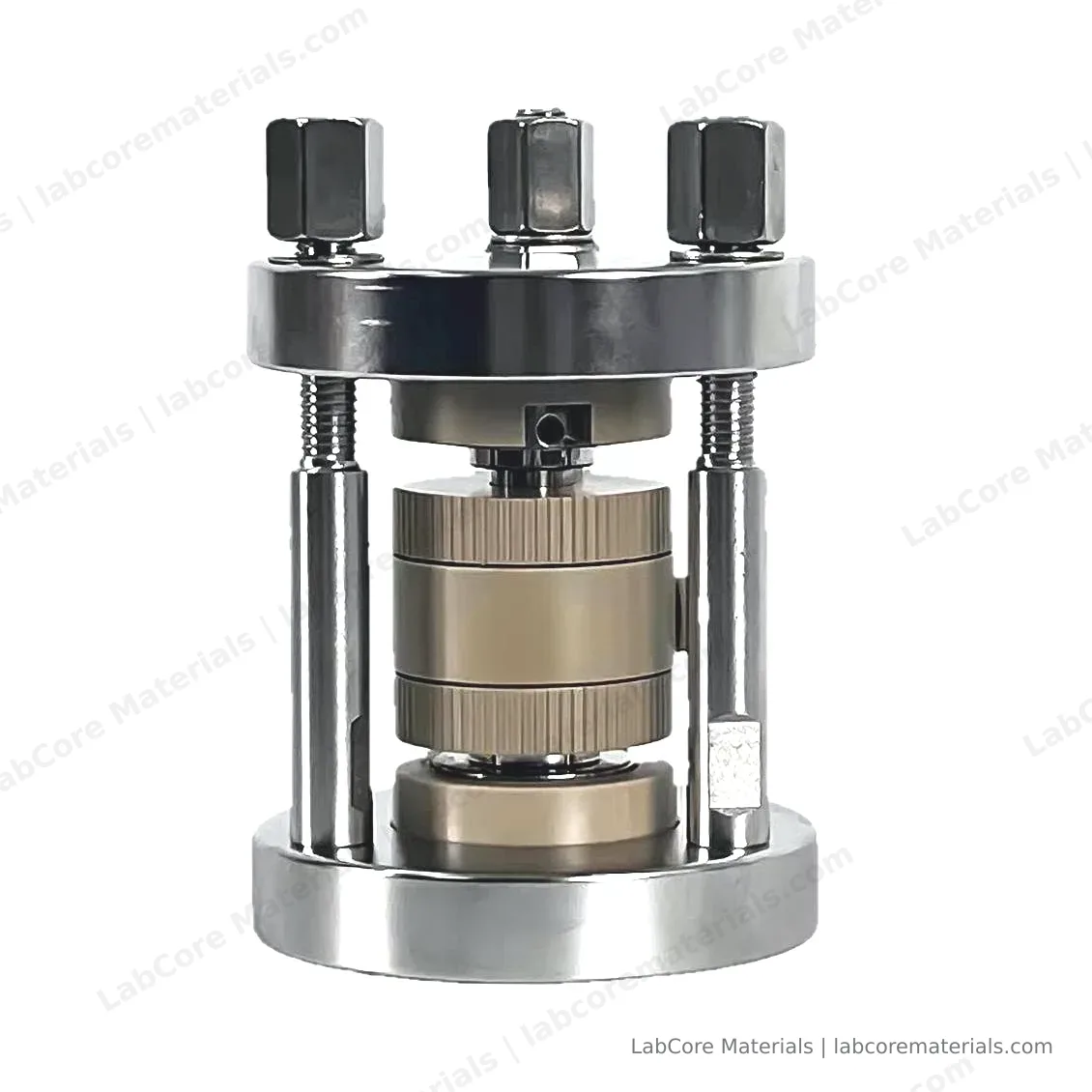
The Solid-State Battery Three-Electrode Test Mold is designed for the scenarios in this article:
- Wide temperature testing: PEEK stable to 200 °C, suitable for Scenario 3 temperature studies
- High-pressure testing: Rated 500 MPa, customizable to 1000 MPa, suitable for Scenario 4 pressure studies
- Long-cycle stability: Split-body design for mid-cycle inspection, suitable for Scenario 5 evolution studies
Product inquiry: business@labcorematerials.com | Quote replied within 48 hours (USD, DDP to major US ports)