
Three Conditions to Fix Before Measurement
Membrane conductivity depends on the measurement direction, the class of material and the temperature. Three conditions must be defined before connecting the cell:
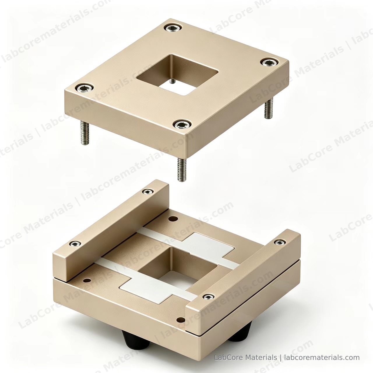
- Direction: along the membrane surface (in-plane) or perpendicular to it (through-plane). The two directions can differ by an order of magnitude on the same membrane, because the conduction path length and the cross-section are different.
- Material: ion-exchange membranes (PEM/AEM, conduction through fixed charge and counter-ions), porous separators (conduction through electrolyte-filled pores), dense solid electrolytes (conduction through lattice or grain boundaries). Each has its own equivalent circuit and error sources.
- Temperature and equilibrium: constant 25 °C, membrane equilibrated in the test solution. A membrane that has not reached equilibrium drifts monotonically over the first few measurements.
This article follows the in-plane method for ion-exchange membranes; the difference between two- and four-electrode arrangements applies to the other two material classes as well.
In-Plane versus Through-Plane Methods
In-plane. A membrane strip sits in the electrolyte and current flows along its surface. Conductivity follows the length direction:
L is the distance between the two voltage probes, w the membrane width, t the thickness. The strip must be longer than the electrode spacing, and width and thickness have to be measured, not assumed.
Through-plane. The membrane separates two compartments and current crosses the surface. Results are usually reported as area resistance:
For porous separators in battery research, the MacMullin number is more common: the ionic resistance of the electrolyte-filled separator divided by that of the neat electrolyte at the same geometry. It folds tortuosity and porosity into one dimensionless quantity, decoupled from absolute thickness, which makes cross-sample comparison possible (Landesfeind et al., J. Electrochem. Soc., 2016, 163: A1373–A1387).
Where the Two-Electrode Error Comes From
In a two-electrode arrangement the same pair of electrodes carries current and senses voltage. The overpotential at the electrode/electrolyte interface adds to the ohmic drop across the membrane, and both appear in the measured voltage, so the resistance comes out too high.
On an impedance spectrum this shows as a large low-frequency semicircle associated with the interfacial capacitance; the high-frequency real-axis intercept is the sum of membrane and solution resistance. Direct DC resistance readings suffer from the same mechanism, where it appears as a drifting value instead of a semicircle.
Raising the frequency reduces the interfacial contribution, but cable inductance at the high-frequency end lifts the curve and shifts the intercept. The reliable route with two electrodes is an equivalent-circuit fit rather than reading the intercept by eye.
Two electrodes remain adequate when the membrane resistance is much larger than the interfacial impedance — thick or poorly conducting membranes — or when the only goal is a relative ranking within one batch.
How Four Electrodes Remove the Polarization
The four-electrode arrangement separates the functions: the outer pair of platinum plates carries current, the inner pair of platinum wires senses voltage. The voltage input impedance is in the megaohm range, so almost no current flows through the sensing circuit, no current crosses the wire/membrane contact, and no interfacial overpotential develops there. The measured voltage drop is the ohmic drop of the membrane segment between the probes.
Sone et al. used exactly this structure to obtain the proton conductivity of Nafion 117 free of electrode polarization (J. Electrochem. Soc., 1996, 143: 1254–1259).
Four electrodes introduce three new error sources, all controlled at assembly:
| Source | Effect | Control |
|---|---|---|
| Probe spacing L | Enters the denominator directly; 1% spacing error gives roughly 1% conductivity error | Fix with a graduated positioning block, measure and record after assembly |
| Contact pressure at the probes | Too little pressure adds contact resistance; too much locally compresses the membrane | Spring-loaded or constant-force clamping, identical across a batch |
| Current bypass | Part of the current flows around the membrane through the solution, lowering the measured resistance | Negligible when electrolyte conductivity is far below the membrane's; otherwise mask the bypass path |
Worked Example
Take 20 mm plate spacing, a 10 mm wide membrane, 50 µm thick. If the four-electrode measurement gives R = 24 kΩ:
The same membrane measured in a two-electrode arrangement might give R = 68 kΩ including interfacial polarization, which computes to 5.9 mS/cm. The two results come from the same membrane; the difference lies in the wiring. This is the main reason values from different papers cannot be compared directly.
A reportable result includes direction, L, w, t, temperature, electrolyte concentration and electrode arrangement. Any missing item makes the number impossible to reproduce.
Where to Read R on the Spectrum
The four-electrode system reduces to R0 + (R1 ∥ CPE):
- R0: the ohmic resistance between the probes, in parallel with the solution path, read at the high-frequency real-axis intercept
- R1 and CPE: residual interfacial and diffusion processes, at mid to low frequency
Fit from 1 MHz to 1 Hz and take the converged intercept, not the real part of a single frequency point. If the imaginary part turns positive at high frequency, the cable or fixture is adding inductance; add a series inductance term to the model, otherwise the fitted intercept is pulled low.
For low-impedance membranes (tens of mS/cm and above), the residual impedance of instrument and cabling becomes a significant fraction of the total. Measure a short-circuit dummy first and subtract it.
Temperature and Equilibrium
- Temperature: 25.0 ± 0.1 °C. Conductivity changes by roughly 2% per degree Celsius, which is enough to make two datasets disagree.
- Equilibration: soak ion-exchange membranes in the test solution for at least 24 h, with one solution change. An unequilibrated membrane drifts monotonically over the first three to five measurements; check equilibrium before suspecting the fixture.
- Concentration: match the solution to the intended operating condition. Ion-exchange membrane conductivity depends strongly on external salt concentration, which is one source of scatter in the literature (Díaz-Milhet and Kamcev, J. Membr. Sci., 2021, 618: 118718).
Common Errors
| Symptom | Cause | Action |
|---|---|---|
| Conductivity too low | Two-electrode data not corrected for interfacial polarization | Switch to four electrodes, or fit an equivalent circuit and take the intercept |
| Same membrane differs by over 20% between runs | Probe spacing or clamping pressure changed | Fix the positioning block, record pressure and spacing |
| Reading drifts downward over time | Membrane not equilibrated, or the solution is taking up water | Extend soaking, seal the solution, hold temperature |
| Unstable high-frequency intercept | Cable inductance, poor contact | Add an inductance term, check connectors, measure the dummy |
| Off by an order of magnitude versus literature | Different direction (in-plane vs through-plane) | Check the direction and geometric constant in the source |
| Dry membrane edge | Solution level below the top of the membrane | Raise the level, keep the measured region fully immersed |
When Each Arrangement Is the Right Choice
| Scenario | Recommended | Reason |
|---|---|---|
| Ion-exchange membrane development, values to be compared with literature | Four electrodes | Removes interfacial polarization, reproducible numbers |
| Membrane resistance far above interfacial impedance (thick, low-conductivity) | Two electrodes | Error share is small, assembly simpler |
| Separator area resistance and MacMullin number for cells | Two electrodes (symmetric cell) | The quantity of interest is the ratio to neat electrolyte; interfaces cancel within one system |
| Temperature sweep in one fixture | Four electrodes | Interfacial impedance changes more with temperature, and a two-electrode setup folds that change into the membrane value |
Both arrangements can be built into the same cell body; only the electrode placement differs. The choice follows the error budget: once interfacial impedance exceeds 10% of the membrane resistance, use four electrodes.
Using the Conductivity Data
Conductivity data serves three purposes: in membrane development, as a quantitative criterion for batch consistency and formulation screening; in cell and system design, for estimating the membrane contribution to the total internal resistance; and in benchmarking against literature, as a check on the measurement protocol. When a value disagrees with published data, verify direction, temperature, concentration and wiring first, before attributing the difference to the membrane itself.
Related Reading
- How to Read an EIS Spectrum — which process each frequency region corresponds to, and what the intercept and the semicircle mean
- Battery Separator Brand Guide — how porosity, wettability and area resistance relate for porous separators
References
- Díaz-Milhet J, Kamcev J. Ionic conductivity of ion-exchange membranes: measurement techniques and salt concentration dependence. Journal of Membrane Science, 2021, 618: 118718. DOI: 10.1016/j.memsci.2020.118718
- Sone Y, Ekdunge P, Simonsson D. Proton conductivity of Nafion 117 as measured by a four-electrode AC impedance method. Journal of The Electrochemical Society, 1996, 143: 1254–1259. DOI: 10.1149/1.1836625
- Landesfeind J, Hattendorff J, Ehrl A, et al. Tortuosity determination of battery electrodes and separators by impedance spectroscopy. Journal of The Electrochemical Society, 2016, 163: A1373–A1387. DOI: 10.1149/2.1141607jes