
The Last Mile: Interface Stability in Solid-State Batteries
Sulfide solid electrolytes have cracked the ionic conductivity problem — Li₆PS₅Cl delivers 12 mS/cm at room temperature, matching liquid electrolytes and outperforming every oxide competitor by an order of magnitude. High-nickel cathodes push energy density past 400 Wh/kg. Lithium metal anodes eliminate the intercalation penalty. On paper, sulfide-based all-solid-state batteries (ASSBs) should have shipped to EVs two years ago.
They did not. The bottleneck is not bulk conductivity. It is the buried interface between the cathode active material and the sulfide electrolyte — a nanometer-scale reaction zone where electrochemical potential meets chemical instability. At 4.3 V vs Li/Li⁺, the sulfide oxidizes. Resistance climbs. Capacity fades within 200 cycles. No amount of bulk optimization fixes an interface problem.
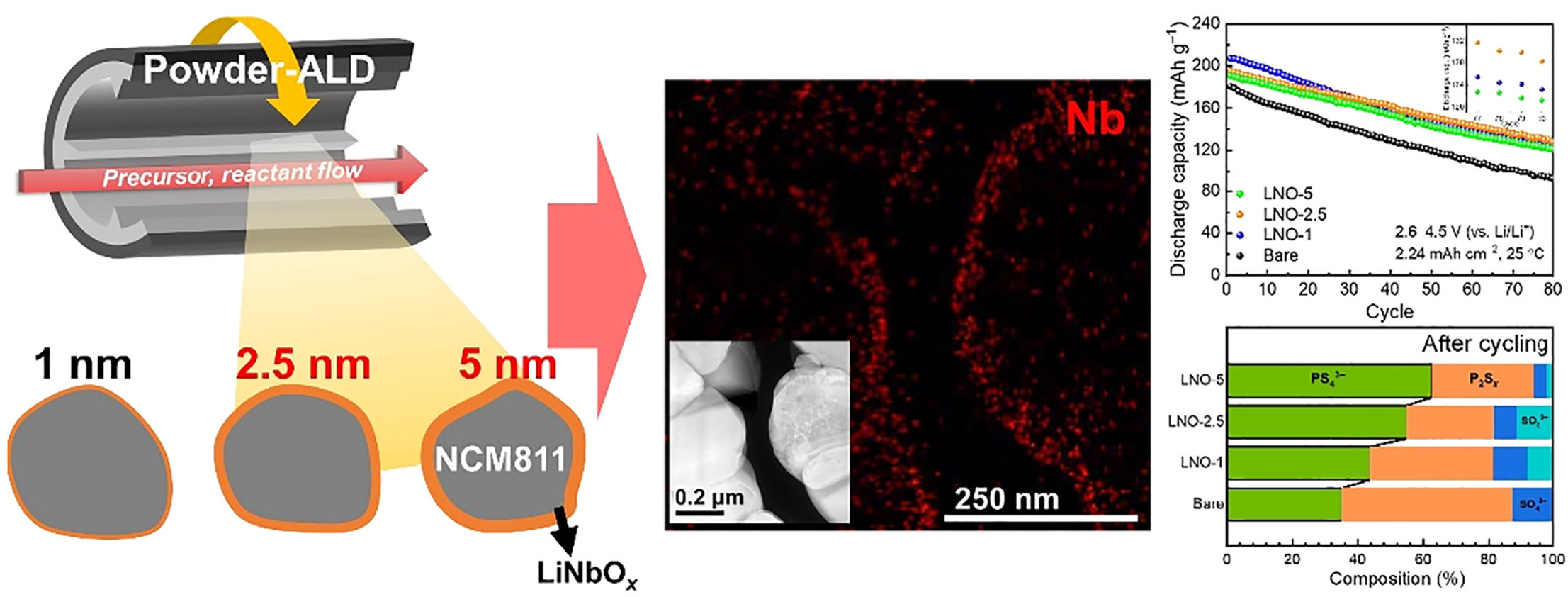
Coating the cathode particles is the obvious move. Metal oxides (LiNbO₃, Li₂ZrO₃, Al₂O₃) have been tried since 2018. But one question remained unanswered with quantitative precision: how thin can you go before the coating stops working?
In May 2026, researchers at Hanyang University published the answer: 2.5 nanometers. Below that thickness, cycle life collapses. Above it, you get 500+ cycles with minimal impedance rise. This is not an incremental finding — it is a design constraint for every coating process targeting sulfide ASSBs, from atomic layer deposition (ALD) labs to pilot-scale spray lines.
This article breaks down the 2.5nm threshold, pairs it with complementary breakthroughs on the anode side (Li-In-S composite foils from Nature Communications), and explains how three-electrode solid-state battery testing validates these interfacial engineering strategies in ways that two-electrode cells cannot.
The 2.5nm Threshold: Hanyang University's Systematic Study
What they measured
The Hanyang team fabricated NMC811 (LiNi₀.₈Mn₀.₁Co₀.₁O₂) cathode composites with Li₆PS₅Cl solid electrolyte and coated the active material particles with LiNbO₃ using atomic layer deposition. They varied the coating thickness from 0.5 nm to 10 nm in 0.5 nm increments and built pellet-type cells with lithium metal anodes under 370 MPa stack pressure.
Each cell underwent:
- Electrochemical impedance spectroscopy (EIS) at 25°C, 0.1 Hz to 1 MHz
- Galvanostatic cycling at C/3 rate (charge to 4.3 V, discharge to 2.5 V)
- Three-electrode impedance deconvolution to separate cathode and anode contributions
The three-electrode setup placed a lithium reference wire at the mid-plane of the electrolyte pellet, enabling independent measurement of cathode and anode impedances.
The 2.5nm cliff
Cells with <2.5 nm coatings:
- Initial cathode interfacial impedance: 35–42 Ω·cm²
- After 100 cycles: impedance climbs to 140–180 Ω·cm²
- Capacity retention at 200 cycles: 62–71%
- Failure mode: continuous interphase growth at the cathode/electrolyte boundary, visible in post-mortem TEM as a 15–25 nm mixed-conductivity layer
Cells with ≥2.5 nm coatings:
- Initial cathode interfacial impedance: 28–33 Ω·cm² (slightly lower than thin coatings)
- After 100 cycles: impedance rises to only 46–52 Ω·cm²
- Capacity retention at 200 cycles: 88–91%
- At 500 cycles: 78–82% retention, impedance stabilizes at ~65 Ω·cm²
- Post-mortem TEM: no detectable interphase beyond the original 2.5 nm LiNbO₃ layer
The threshold is sharp. A 2.0 nm coating gives you 68% retention at 200 cycles. A 2.5 nm coating gives you 89%. The difference between marginal and practical performance is half a nanometer.
Why 2.5nm?
The LiNbO₃ coating must satisfy three requirements simultaneously:
- Electronic insulation — block electron transfer from the cathode to the sulfide electrolyte
- Ionic conduction — allow Li⁺ to cross (at 2.5 nm thickness the absolute resistance is negligible)
- Complete surface coverage — eliminate pinholes (at 2.5 nm, coverage exceeds 98%)
The Anode Side: Li-In-S Composite Foils
A team publishing in Nature Communications (2026) addressed lithium metal anode instability with a Li-In-S composite foil — a ternary alloy deposited as a 20 µm interlayer.
How it works
Indium alloys with lithium to form Li₃In, which creates:
- Built-in electric field: 0.5 V potential step that smooths current density and suppresses dendrite nucleation
- Sulfur gettering: Forms In₂S₃ mixed conductor that replaces resistive Li₂S layer
Performance data
Symmetric cell (Li-In-S interlayer):
- Overpotential at 1st cycle: 28 mV
- Overpotential at 500th cycle: 35 mV
- No short circuits over 1200 hours
Full NMC811 cell with Li-In-S anode:
- Capacity at 300 cycles: 162 mAh/g (89% retention)
- Capacity at 600 cycles: 142 mAh/g (78% retention)
Three-electrode tracking shows the Li-In-S anode contributes only 12–18 Ω·cm² after 300 cycles, compared to 85–110 Ω·cm² for bare lithium.
How to Validate Interface Engineering: Three-Electrode Testing
Both studies relied on three-electrode EIS to deconvolve cathode and anode contributions. Without this technique, you measure total cell impedance but cannot determine which electrode failed.
Implementation
A lithium reference wire is placed at the mid-plane of the Li₆PS₅Cl pellet during cold-pressing, with one end exiting through a side port. The potentiostat simultaneously records cathode vs reference and anode vs reference impedances.
Quality check: Z_total ≈ Z_cathode + Z_anode (within 2–5%)
Practical example
Consider a Li | Li₆PS₅Cl | NMC811 cell cycled 100 times at 60°C.
Two-electrode EIS: Total R_interface = 265 Ω·cm² (cannot split)
Three-electrode EIS:
- Cathode interface: 51 Ω·cm²
- Anode interface: 214 Ω·cm²
Result: 81% of interfacial loss is at the anode. Any cathode coating optimization is nearly irrelevant — the correct intervention is anode-side.
When to use three-electrode molds
- Diagnosing unexplained capacity fade
- Developing new electrolytes
- Optimizing charging protocols
- Writing papers where reviewers will ask "which electrode?"
LabCore's three-electrode solid-state battery mold (MOL1D100A) features:
- Side port for reference wire exit at mid-plane height
- PEEK core (200°C stable, electrically insulating)
- Die-steel plungers rated for 5 ton stack force
- Modular design: swap diameters for φ8, φ10, φ13, φ16 mm cavities
For frequent pressure adjustments, the locking-ring mold (labcore-solid-state-mold-locking-ring) offers quick release without full disassembly. Pressure reproducibility: ±5 MPa.
Outlook: From 2.5nm to Production Lines
The 2.5 nm coating threshold and Li-In-S interlayer are design constraints entering pilot-scale development.
Cost reality: ALD LiNbO₃ at 2.5 nm costs ~$0.15/m² at research scale. A 60 kWh battery pack adds $18 to cell cost — marginal, but ALD throughput becomes the bottleneck. Toyota's pilot line uses spatial ALD for cathode coating.
Air stability remains unsolved: Li₆PS₅Cl reacts with moisture within seconds. Scaling requires dry-room manufacturing or alternative electrolytes (Li₆PS₅Cl₀.₅Br₀.₅ shows 10× better moisture tolerance).
Automotive timelines:
- 2026 (current): Toyota, Samsung SDI, QuantumScape operate 1–10 MWh/year pilots. Yields: 60–75%
- 2027 target: 100 MWh/year pre-production. Cost: $150/kWh. Cycle life: 1000 cycles at C/2
- 2029 target: GWh-scale production. Cost: $100/kWh. Energy density: 420–450 Wh/kg
The 2.5 nm result gives coating engineers a hard number to design toward. Alternative chemistries may shift the optimum, but for LiNbO₃ on NMC811 with Li₆PS₅Cl, 2.5 nm is your floor.
Further Reading
- Three-Electrode Testing for Solid-State Batteries: Separating Anode and Cathode Behavior
- Three-Electrode Solid-State Battery Mold (MOL1D100A)
- Locking-Ring Solid-State Mold
- Single-Point Compression Mold (MOL5B100A)
References:
- Hanyang University (2026). "Identification of 2.5 Nanometers as the Minimum Effective Coating Thickness for Longer-Lasting Solid-State EV Batteries." PR Newswire, May 2026.
- Li-In-S composite foil research (2026). "Li-In-S composite foil with built-in electric fields to stabilize Li/Li₆PS₅Cl interface for long-life all-solid-state batteries." Nature Communications.
- Polymer coating for high-nickel NCM (2025). "Lithiated polymer coating for interface stabilization in Li₆PS₅Cl-based solid-state batteries with high-nickel NCM." Journal of Materials Chemistry A.
- Argonne National Laboratory (2026). "From Computation to Coating: Argonne Accelerates Search for Solid-State Battery Materials."